
Prerequisite Knowledge:
Lift is the force that keeps the aircraft in the air, but how exactly is this force created?
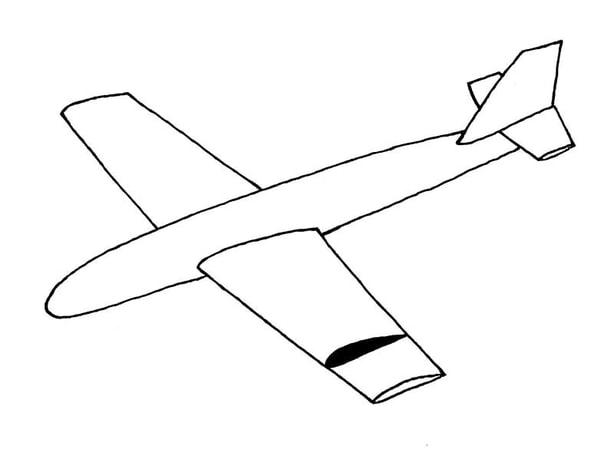
The Aerofoil (or Airfoil):
The shape of a wing's cross section is referred to as an aerofoil. An aerofoil can take on many shapes, depending on what is needed of it.
Lift is the force that keeps the aircraft in the air, but how exactly is this force created?
The Aerofoil (or Airfoil):
The shape of a wing's cross section is referred to as an aerofoil. An aerofoil can take on many shapes, depending on what is needed of it.
Aerofoils can take on any particular shape, but before discussing how aerofoils generate lift, there are several parts of an aerofoil that must be identified.
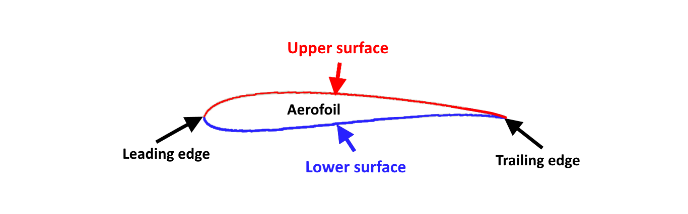
- Aerofoil: Any shape that produces lift
- Leading edge: The forward edge of an aerofoil, which comes in contact with the airstream first.
- Trailing edge: The aftward edge of an aerofoil, towards the rear.
- Upper surface: The top surface of an aerofoil.
- Lower surface: The bottom surface of an aerofoil.
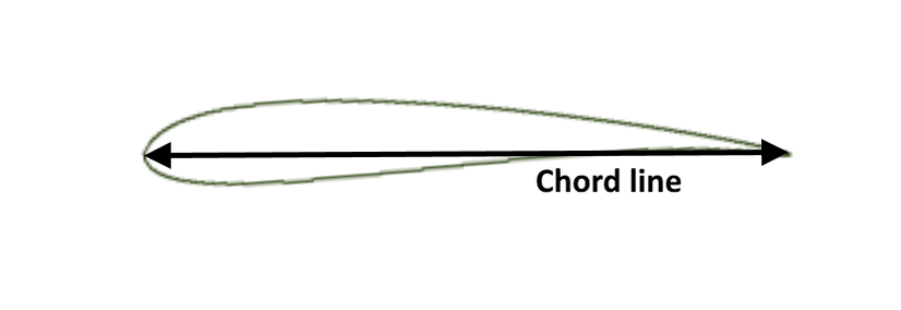
- Chord line: A straight line drawn from the leading edge to the trailing edge.
- Chord length: The distance between the leading and trailing edges.
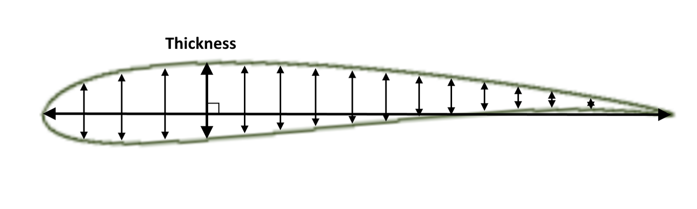
Thickness: The distance between the upper and lower surfaces at any point along the aerofoil, measured perpendicular to the chord line.
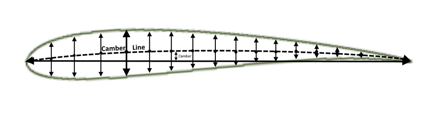
- Mean camber line: A representation of the average curve of the aerofoil; the mean camber line passes through the exact middle of the aerofoil (the midpoints of all the thickness lines).
- Camber: The distance between the chord line and the camber line at any point along the aerofoil, measured perpendicular to the chord line.
More definitions will be added as this article progresses, but these are the basic ones to know.
Lift Generation:
There are several factors that play a role in how aerofoils produce lift.
The Bernoulli principle
Lift Generation:
There are several factors that play a role in how aerofoils produce lift.
The Bernoulli principle
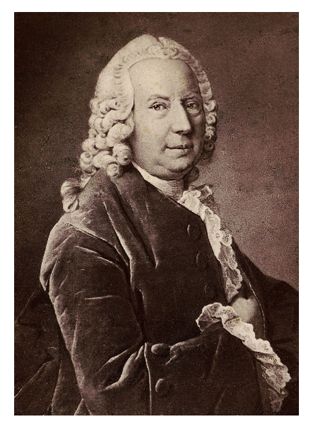
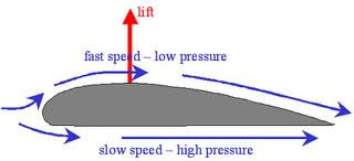
So this dude is Daniel Bernoulli (one of like, seven different Bernoullis), and in elementary school you probably learned his principle regarding lift production. The Bernoulli principle states that air flowing over the curved upper surface of an aerofoil has to travel a longer distance, so it accelerates, and travels faster than the air travelling under the flatter lower surface of the aerofoil. As the air passing over the upper surface speeds up, its pressure decreases. This creates an area of lower pressure along the upper surface and higher pressure along the lower surface, exerting a force on the aerofoil in an upwards direction (lift).
There is another principle that contributes to how aerofoils produce lift, and for that, I introduce you to our second dude.
The Newtonian/Flow Turning Principle
The Newtonian/Flow Turning Principle
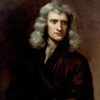
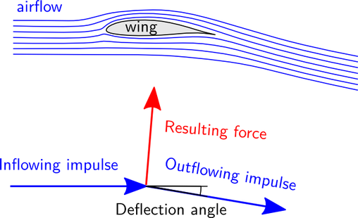
This other dude is Sir Isaac Newton, and his third law of motion also helps explain how an aerofoil produces lift. The flow turning principle states that as the aerofoil comes in contact with the airstream, the lower surface redirects some of the air downwards, creating an upwards force due to Newton's third law of motion (every action has an equal and opposite reaction, air being displaced downwards generates an upwards force). However, the upper surface of an aerofoil can also aid in this. In cambered aerofoils (aerofoils with a curved upper surface), the air naturally follows the contour of the upper surface, which also redirects it downwards at the trailing edge. This helps generate more lift, as more air is being displaced downwards by not just the lower surface, but the curved upper surface as well.
There is one more factor that is necessary for the explanation of lift production, and that is angle of attack.
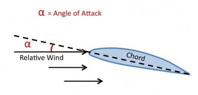
- Relative wind: The direction of the airflow as it reaches the aerofoil.
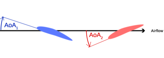
- Angle of attack (AoA): The angle between the chord line and the relative wind. The greater the angle of attack, the more air the aerofoil deflects downwards, creating higher pressure below the aerofoil and the more lift. Lift generated by this technique is not the same as flow turning or the Bernoulli principle. The Bernoulli principle relies on the the different speeds of the air streams to create a difference in pressure above and below the aerofoil. The flow turning principle relies on air following the curved upper surface and getting redirected downwards. An aerofoil flying at a postive angle of attack (as shown in the diagram) simply forces the air downwards with its lower surface, generating lift. When the chord line is above the relative wind, the angle of attack is positive, but when the chord line is below relative wind, the angle of attack is negative. In the image below, AoA1 represents a positive angle of attack, whereas AoA2 is negative.
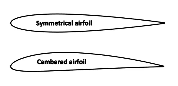
- Symmetrical aerofoil: An aerofoil where the upper and lower surfaces are the same. Symmetrical aerofoils produce no lift at zero degrees angle of attack.
- Cambered/asymmetrical aerofoil: An aerofoil where the shapes of the upper and lower surfaces are different. Cambered aerofoils produce some lift at zero degrees angle of attack.
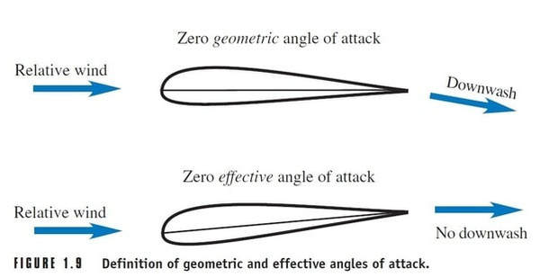
- Zero lift line: A line representing the angle of attack where the aerofoil produces no lift. For symmetrical aerofoils, the zero lift line is the same as the chord line, since they produce no lift at zero degrees angle of attack.
Cambered aerofoils are examples of optimized aerofoils. Thanks to their longer curved upper surface, they can use the Bernoulli and flow turning principles to generate lift at zero degrees angle of attack. This means that they have a zero lift line; the zero lift line being the angle of attack where it truly produces no lift.
Symmetrical aerofoils must fly at a positive angle of attack to generate lift. Because there is no uniquely curved upper surface, no air is directed downwards at zero degrees angle of attack, and there is no speed difference between the upper and lower air streams, which means no lift from the Bernoulli principle.
At high angles of attack, significant amounts of drag are produced, which is not optimal. Aircraft designed primarily for level flight (airliners, small general aviation aircraft etc.) have optimized cambered aerofoils. This means their wings still produce enough lift at low angles of attack, where there is the least drag.
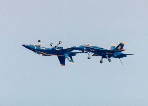
However, aerobatics or fighter aircraft do not benefit from cambered aerofoils as they also need to be able to fly inverted. Lift is always produced upwards relative to the aerofoil. This means that when an aircraft is flying inverted, a cambered aerofoil would actually pull the aircraft to the ground (even at zero degrees angle of attack), which is not ideal for aerobatic/fighter aircraft. An inverted cambered aerfoil would have to fly at an extreme angle of attack in order to counteract it's lift from the Bernoulli/flow turning principles, which is not ideal to the drag that is produced. In these applications, symmetrical aerofoils are ideal, as the lift they generate is solely dependent on the angle of attack. With symmetrical aerofoils, as long as the pilot keeps the aircraft slightly pitched up (towards the sky) in inverted flight, the aerofoil will generate lift in that direction (towards the sky), keeping the aircraft in the air.
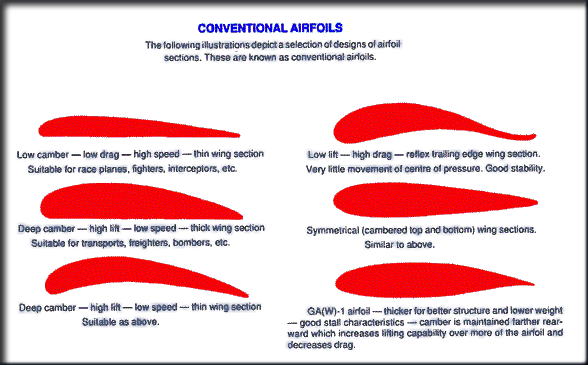
This chart shows different shapes of aerofoils, and what their applications are. Aerofoils with a significant camber are better suitied for low speed non-inverted flight since they take advantage of the Bernoulli/flow turning principles. Aerofoils with less of a camber (more symmetrical) are better for high speed inverted flight, since they are more versatile due to the fact that they do not use the Bernoulli/flow turning principles.
The Lift Equation:
The Bernoulli lift equation is used to calculate the theoretical lift generated by an aerofoil. The equation is based off of conservation of fluid energy; this means that it works for all types of aerofoils.
The Bernoulli lift equation is used to calculate the theoretical lift generated by an aerofoil. The equation is based off of conservation of fluid energy; this means that it works for all types of aerofoils.
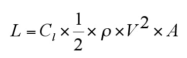
L = The force of lift
Cl = Coefficient of lift (unique for every aerofoil, also depends on angle of attack and other factors)
p (rho) = Density of fluid
v = Velocity of fluid relative to the aerofoil
A = Surface area of the wing
With this equation, it is easy to see how all of the different factors come together for an aerofoil to generate lift. This formula will be looked at in more detail in later articles.
That's it for advanced lift generation! The next article will look at the drag force in more detail.
